10S, 13S, 14S, 16S, 20S. Waterproof boards have a protective function and balance of the series
PRICES:
10S BMS 40A (36V bms; 42V bms), common port – 90 BGN
13S BMS 40A (48V bms; 54.6V bms), common port – 110 BGN
14S BMS 40A (52V bms; 58.8V bms), common port – 120 BGN
16S BMS 40A (60V bms; 67.2V bms), common port – 120 BGN
20S BMS 60A (72V bms; 84V bms), common port – 120 BGN
13S BMS 40A (48V bms; 54.6V bms), common port – 110 BGN
14S BMS 40A (52V bms; 58.8V bms), common port – 120 BGN
16S BMS 40A (60V bms; 67.2V bms), common port – 120 BGN
20S BMS 60A (72V bms; 84V bms), common port – 120 BGN
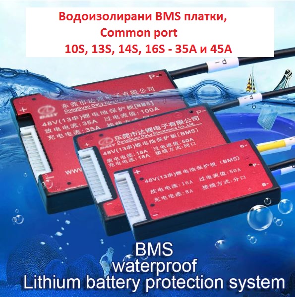
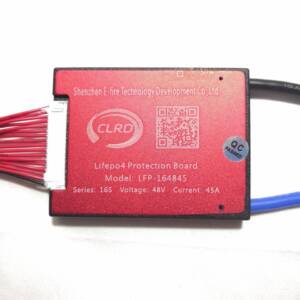
Waterproof BMS boards with Common port, supporting regeneration (battery charging when stopping), with direct discharge current 35A or 45A, for lithium-ion batteries.
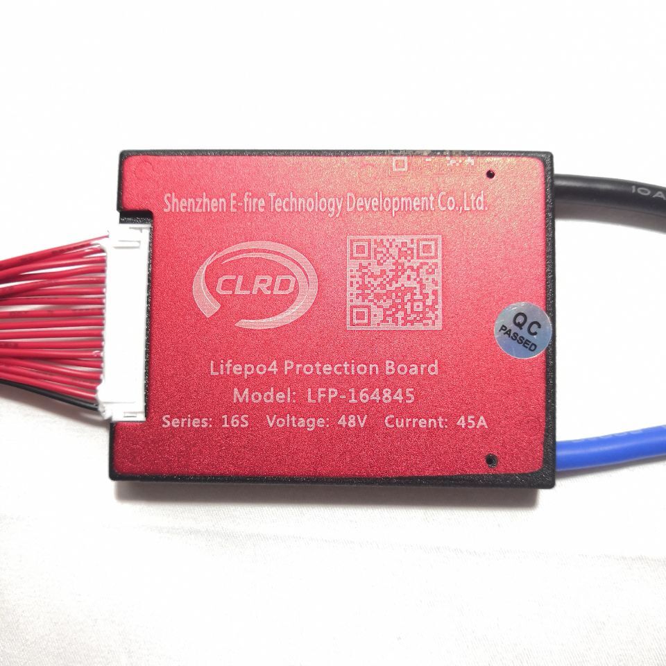
With different voltages - 10S, 13S, 14S, 16S. The boards have protection function and series balance!
The boards withstand peaks up to 100A (for the 35A model) and up to 180A (for the 45A model).
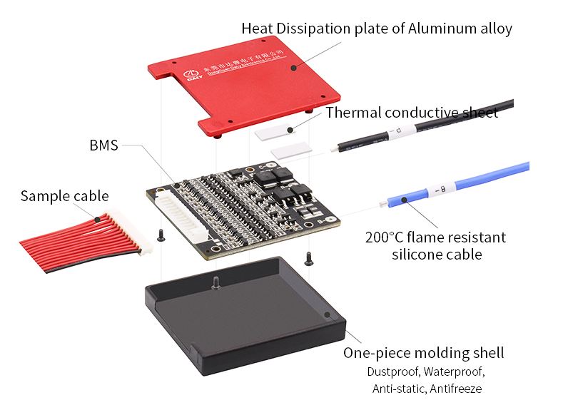
The housing is waterproof;
They have a built-in radiator for heat dissipation
They have a built-in temperature sensor for thermal protection.
Charging current / the discharge current is 35A and 45A, според модела.СХЕМА НА СВЪРЗВАНЕ: Виж снимка след описанието
 Recommendation: When making a 10S battery, 13S, 14S, 16S series, it is good that the individual elements are at the same voltage (equally charged / diluted).
If they are not - load them separately and then use them in batches.
To check the condition of the battery - if the voltage of a given / certain series fall faster, it is weak in these series / damaged battery.
It is not good to mix old or weak, or different battery models together!
The state of the assembled battery is relatively equal to the state of the weakest element in it!
With different voltages - 10S, 13S, 14S, 16S. The boards have protection function and series balance!
The boards withstand peaks up to 100A (for the 35A model) and up to 180A (for the 45A model).
The housing is waterproof;
They have a built-in radiator for heat dissipation
They have a built-in temperature sensor for thermal protection.
Charging current / the discharge current is 35A and 45A, според модела.СХЕМА НА СВЪРЗВАНЕ: Виж снимка след описанието
SPECIFICATION:
Overcharge protection 4.25 ± 0.025V
Recharge time – 0.5S
Release after re - discharge V – 4.19 ± 0.05V
Rated voltage to start cell balancing – 4.18V
Direct current at balance up to 45A ± 5mA
Cell overload protection 2.8 ± 0.05V
Discharge response time – 0.5S
Recovery recharge – 3.0V ± 0.05V
Voltage for overload detection 150mV
Response time in case of overvoltage detection – 9mS
Overload detection condition: disconnects the load
Conditions for short circuit protection: short circuit with external load
250uS short circuit detection delay
Short circuit protection release state: Switch off the load
Temperature protection
Conduction resistance of the main circuit ≤ 10 mΩ
Operating current with independent power ≤ 40uA
Stand-alone supply current consumption (redischarge) ≤ 20uA
Operating temperature range -30 / + 80 Celsius
The overload voltage of the lion ion integration circuit is 4,25 V.
The overdischarge voltage is 2.7V. The balance is 4.18V.
BMS 35A – 73*61*9mm
BMS 45A – 80*65*9mm
CONNECTION INSTRUCTIONS:
1. The balance socket (the ribbon connector from the BMS) is disconnected!
2. The cables of the tape socket to the battery series are soldered in series. On the 1st cable (the black one) solder the first "-" of the battery (0V), and on each subsequent red cable in turn is soldered on each subsequent bridge (3.7V; 7.4V; 11.1V … etc.). On the last + the last red cable from the ribbon balance connector is soldered to the battery.
3. Be sure to measure the voltages between the series with a multimeter on the balance connector! There should be no sequence error! "-" of the multimeter is placed on the black wire from the connector, and the "+" of the multimeter is placed consecutively on each subsequent red. The voltages must be increased in equal steps with each measurement. If there is a wiring error, be sure to fix it, otherwise, after switching on, the board will be damaged!
4. Solder B- battery "-" cable;
5. The balance tape socket in the BMS is switched on;
6. The voltage between B is measured with a multimeter- thick cable and + of the battery. The voltage as a value must be the total voltage between "+" and "-" of the battery
7. The main one is soldered + of the battery, from + on goods and + on the charger.
8. On R.- are soldered "-" to the load and the charger.
 Recommendation: When making a 10S battery, 13S, 14S, 16S series, it is good that the individual elements are at the same voltage (equally charged / diluted).
If they are not - load them separately and then use them in batches.
To check the condition of the battery - if the voltage of a given / certain series fall faster, it is weak in these series / damaged battery.
It is not good to mix old or weak, or different battery models together!
The state of the assembled battery is relatively equal to the state of the weakest element in it!

Reviews
There are no reviews yet.